
About Services Capabilities Process Work Sectors Contact

AL-SHAMAA · ENGINEERING SERVICES AND CONSULTANCY

Reinforcement detailing · BIM · Structural design

Precision in every single bar.

AL-Shamaa turns structural intent into buildable detail — accurate reinforcement shop drawings, coordinated BIM models and dependable design support, from straightforward elements to highly complex geometries.

0
Core service lines
0 + 0
Drafting & BIM workflows
0
Checked before issue
Construction & Design Scroll
About the practice

A dynamic engineering practice built around accuracy, coordination and buildability.

We specialise in reinforcement detailing, BIM modelling and structural design services. Our team delivers precise and dependable detailing for a wide range of structures — from straightforward elements to highly complex forms — using both advanced BIM platforms and conventional 2D drafting techniques, depending on what the project actually needs.

Beyond detailing, we provide design services including structural analysis and the design of support systems for solar panels. The goal is always the same: add technical value, reduce on-site conflicts, and streamline construction through coordinated, buildable, cost-effective solutions.

See how we work

0
Core service lines
2D + 3D
Delivery methods
0
Independently checked
1:1 model : schedule
Single source of truth

Our vision — to revolutionise the construction industry by delivering precise, intelligent and integrated engineering solutions that drive efficiency, accuracy and sustainable growth.

What we deliver

Three disciplines,
one coordinated output.

Every deliverable is produced against the project's own standards and checked before it leaves the office — so what reaches site is clear, complete and ready to build.

01

Shop Drawings

Highly accurate reinforcement shop drawings tailored to each project — clear, fully dimensioned and detailed for the people placing the steel.

  • Reinforcement detailing for all structural elements
  • Bar bending schedules and quantity take-off
  • Simple structures through to complex geometries
  • 2D drafting where it suits the project best
02

BIM Services

Advanced Building Information Modelling that carries real construction geometry — so conflicts are resolved in the model, not on the slab.

  • 3D Modeling & Shop Drawings
  • Clash Detection & Multi-Disciplinary Coordination
  • BIM Management & Standards Consulting
  • As-Built Modeling
03

Design

Comprehensive design services — structural analysis and the design of support systems for solar panels, grounded in practical engineering judgement.

  • Structural analysis and member design
  • Solar panel support system design
  • Load path and connection checks
  • Cost-effective, buildable solutions
Why AL-Shamaa

Technical value,
added early.

Detailing is where design meets reality. We use that position to remove ambiguity before it becomes a delay, a variation, or a crowded bar zone nobody can place.

Both worlds: advanced BIM and traditional 2D drafting — chosen per project, not per habit.

Some projects want a fully modelled rebar environment. Others need fast, clean 2D output against an established site workflow. We are fluent in both and pick the method that serves the programme.

3DBIM platforms
2DCAD drafting
1Coordinated set

Complex geometry, resolved

Curved walls, transfer structures, sloping slabs and congested nodes — detailed so the steel actually fits.

Fewer conflicts on site

Clashes and buildability issues are caught in the model and the check, before they cost programme time.

Standards-aligned

Deliverables align with your project requirements, client templates and industry standards.

Sustainable by design

Solar support structures and efficient steel arrangements that reduce waste and rework.

One point of contact

A multidisciplinary team that stays with your project from first model to final issue.

How a package runs

From consultant
drawings to site.

A predictable route through every reinforcement package, with the checking built in rather than bolted on at the end.

01

Brief & review

We review the consultant's drawings, specification and standards, agree the delivery method — BIM or 2D — and raise technical queries early.

Inputs locked
02

Model or draft

Reinforcement is modelled in 3D or drafted in 2D against the agreed conventions, element by element, with schedules generated from the same source.

BIM · CAD
03

Coordinate & clash

Rebar is checked against embeds, openings, services and adjacent pours so congestion and clashes are resolved before issue.

Buildability
04

Check & issue

An independent check covers geometry, laps, covers, bar marks and schedules. Nothing leaves the office unchecked.

QA gate
05

Site support

We stay available through construction for RFIs, revisions and as-built updates — keeping the drawing set true to what is actually being built.

Through delivery
Selected work

Two projects.
Nothing standard in either.

One reinforcement package where every column is raked, and one solar plant where the wind rather than the weight decides the steel. Both were modelled before anything was drawn, and both were issued as documents the site could build straight from.

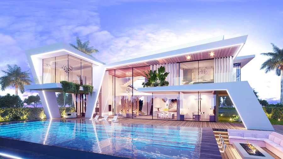
Ohana Villas — a contemporary villa of white, inclined and cantilevered volumes above a reflecting pool.
Case study 01

Ohana Villas — Phase I2

Damour · Chouf, Lebanon

A private villa development where the structure is the architecture: raked reinforced-concrete columns carry the upper floor and the cantilevered roof, so almost nothing about the reinforcement repeats. We modelled the ground-floor-to-first-floor columns in full 3D, worked out the bar arrangement where each inclined shaft lands, and issued a coordinated set of elevations, plans and bar bending schedules.

Scope
Reinforcement shop drawings & BBS
Elements
Inclined columns, flat slabs, footings
Method
3D rebar model → model-driven drawings
Two 3D views of the reinforcement in inclined Column 1, showing starter bars, main bars and links passing through the slab.
Column 1 — 3D reinforcement elevations
3D reinforcement model of the twin inclined Columns 2 and 3 and the beam spanning between them.
Columns 2 & 3 — 3D reinforcement elevation
Reinforcement elevation of the inclined Columns 2 and 3 with bar marks, spacings and cut lengths annotated.
Reinforcement elevation
Reinforcement plans of Columns 2 and 3 at two floor levels, with bar marks and dimensions between grids A and B.
Column plans, two levels
Bar bending schedule listing position, quantity, diameter, cut length and bending shape for every bar mark.
Bar bending schedule
01

The challenge

Every column on this elevation is raked, and each one meets its slab at a different angle and a different level. Standard column details applied nowhere.

02

The approach

The whole ground-to-first-floor zone was built as a 3D rebar model first, so laps, covers and the congested column-to-slab junctions were settled where they could actually be seen.

03

The outcome

Elevations, plans, 3D views and the bar bending schedule all came off that one model.

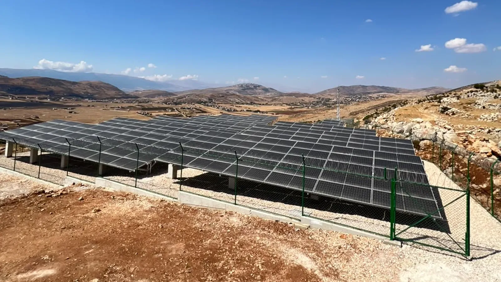
The completed solar plant on a Bekaa hillside — rows of panels on concrete plinths inside a perimeter fence, with the valley and mountains behind.
Case study 02

Anjar–Kherbet Rouha Solar Plant

Bekaa, Lebanon

A ground-mounted PV plant on an exposed ridge, where the panels weigh almost nothing and the wind decides the structure. We set out the array, ran the support tables through a wind simulation, designed the bolted base connections and their anchors against the uplift that came out of it, and sized the spread footings that hold the whole thing down.

Scope
PV support structure analysis & design
Elements
Steel tables, base connections, spread footings
Method
3D wind simulation → connection & footing design
Site plan of the photovoltaic array: ten panel strings labelled S1 to S10 set out on a lettered and numbered grid across the plot.
Array layout — ten strings across the site
Wind pressure map in kilopascals across the 3D model of a panel support table, from a 45 metre-per-second wind simulation.
Wind pressure map — 45 m/s simulation
3D view of a support frame base: box sections and an angle brace landing on a plate anchored into a concrete pedestal, above the cross-section schedule.
Base connection — members and anchors
Equivalent stress plot on the base plate under the governing load combination, with each of the four anchors listed and its utilisation checked.
Base plate — stress and anchor checks
Spread footing design output: pad and pedestal geometry dimensioned, with the concrete strength and reinforcement grades listed below.
Spread footing — geometry and materials
The finished array from ground level: panels carried on galvanised steel tables over a gravel bed, with the Bekaa hills beyond.
The tables as built, on site
01

The challenge

The panels are light and the ridge is exposed, so wind governs rather than gravity — uplift on the tables, tension in the anchors, overturning on the pads.

02

The approach

The tables were simulated in 3D so the pressure they actually see drove the member sizes, instead of a blanket coefficient applied to the whole array.

03

The outcome

Members, base connections, anchors and footings all sized off one set of load cases, with the governing anchor left at 77 % of capacity.

Where we work

Any scale.
Any complexity.

Reinforcement detailing and design support across the structures that make up construction and design programmes.

Residential & mixed use

Cores, slabs, shear walls and podium transfers.

Commercial

Frames, basements and long-span floor systems.

Infrastructure

Retaining walls, culverts, abutments and decks.

Industrial

Foundations, pits, machine bases and plant structures.

Solar & renewables

Panel support systems, ballast and pile foundations.

Complex geometry

Curved, sloping and irregular forms modelled in 3D.

Start a conversation

Send us the drawings.
We'll tell you what it takes.

Share a specification, a set of consultant drawings or just a scope outline. We'll come back with the delivery method, programme and a clear price for the package.

Company
AL-Shamaa Engineering Services and Consultancy
Industry
Construction & Design
Services
Shop Drawings · BIM · Design